


Introduction
A split-ring planetary gearbox is a particular form of planetary gear system which may give you a very excessive gear discount ratio in a really small kind issue.
On this idea particularly, we obtain a discount of 180:1 in a gearbox that’s lower than a centimeter thick. That’s, the motor rotates the solar gear by one full rotation in round 20 seconds and it interprets to a one output gear rotation in a single hour!
An outline of the idea gearbox
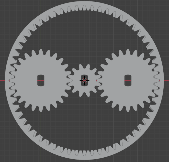
In my design proven under I’ve a single solar gear with 12 module-1 enamel, two planet gears with 24 module-1 enamel every, and two inside ring gears. The ring gear on the highest has 60 module-1 enamel and the decrease one has the identical diameter however has two much less enamel and isn’t technically module-1 anymore. Regardless of that, it meshes rather well with the planet gears as a result of given the big diameter, and small distinction in enamel rely, the distinction in modules could be very small.
Notice: The module is m = d / z, the place m is the module, d is the pitch circle diameter, and z is the variety of enamel
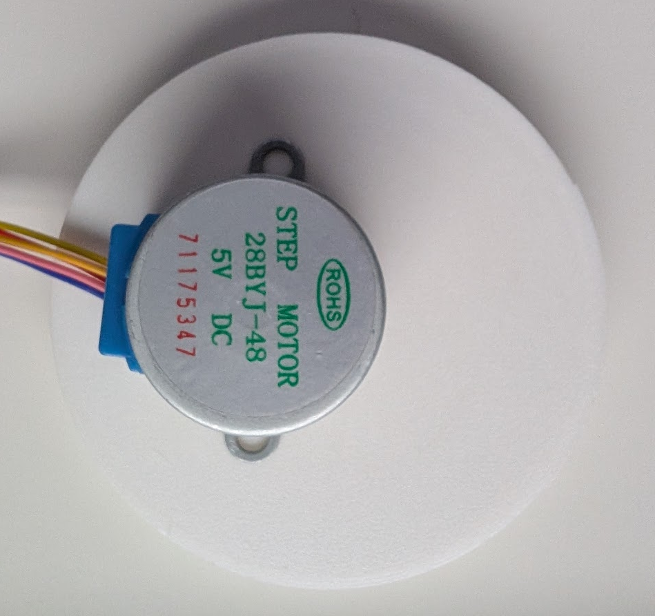
The ultimate gearbox meeting achieves a 180:1 gear discount ratio. It is a large discount. It might be a really sluggish pace for many functions. It’s even slower motor as I’m testing it with a 28BYJ-48 stepper motor. However there’s an excellent purpose for its sluggish pace contemplating the applying I take into account for it. I need to obtain a excessive angular decision for a star-tracking software. It’s going to require sluggish sidereal movement (one rotation in ~24 hours). Excessive pace will not be one thing I want for the applying.
The 28BYJ-48 motor has a 4096 step decision in a single rotation when utilizing half-stepping. This interprets to a 737,280 step decision of the output gear. It will give me a 1.76 arcsecond decision. One arcsecond is one-3600th of a level, or one-1,296,000th of a full circle. My guess is, this ought to be a ok decision to not smear stars throughout pixels for a 135 mm lens’s area of view.
The cut up rings
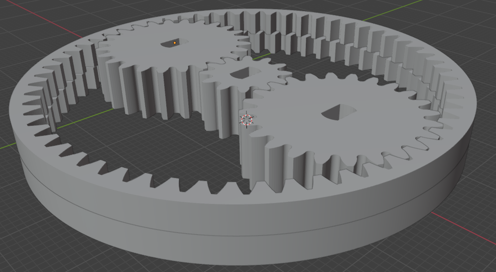
The solar and the planet gears are 8mm thick every. The cut up rings are 4mm thick and stacked on each other.
The cut up ring on high has 60 inside enamel and the one under it has 58 enamel. The ring on the underside is mounted, whereas the highest ring is free to maneuver. This high ring delivers the output. As seen within the first image, the 2 rings match enamel precisely at solely two locations. These are the place the planet gears slot in.
Gear discount
There are two gear discount levels on this gearbox. The primary one is a straightforward planetary gear discount. It is a 6:1 discount. Which means, 6 rotations of the solar gear (12 enamel) equates to 1 rotation of a planet gear (24 enamel) across the mounted ring (60 enamel).
Stage-1 planetary discount (i) = 1+(60/12) = 6The second stage considerations the interplay of the planet gear with cut up rings. Think about when the planet gears transfer, they push their means in as they rotate. This causes the free high ring to maneuver so very barely to accommodate the planet enamel into the hole. When the planet gear rotates by 180 levels, the ring rotates precisely by one enamel.
Within the following magnified model, think about the pink enamel are mounted. The blue enamel are free to maneuver. Because the black (planet gear) pushes its enamel in, the blue gear advances ever so barely to grow to be meshed on the place the planet gear pushes in.

Thus by the point a planet gear strikes by 360 levels, the ring gear strikes precisely by two enamel. That’s 2 out of 60 enamel in 360 levels, or 12 levels. 30 revolutions of a planet gear strikes the ring gear in a single circle.
A 6:1 discount within the first stage (sun-planet), adopted by a 30:1 discount within the second stage (planet-ring) equals to a complete of 180:1 discount from solar to ring.
Involute enamel profile calculation
I used blender to design the gears. I began by calculating the gear enamel profile equation utilizing this software – Inside/Exterior Gear Calculator. Plugging in 24 for exterior and 60 for inside gear with a strain angle of 20 levels gave me the next equations.
Planet gear:
x-equation = 11.276 * (cos(u * 0.574) + u * 0.574 * sin(u * 0.574))
y-equation = 11.276 * (sin(u * 0.574) - u * 0.574 * cos(u * 0.574))
Prime ring inside gear (60 enamel):
x-equation = 28.191 * (cos((0.2413 + u * 0.237)) + (0.2413 + u * 0.237) * sin((0.2413 + u * 0.237)))
y-equation = 28.191 * (sin((0.2413 + u * 0.237)) - (0.2413 + u * 0.237) * cos((0.2413 + u * 0.237)))
I used 24 and 58 to calculate the underside gear enamel profiles. Later I merely elevated gear’s diameter to match the 60 enamel gear. This adjustments the module barely, however not by a lot that meshing turns into a difficulty.
Backside ring inside gear (58 enamel):
x-equation = 27.251 * (cos((0.2360 + u * 0.246)) + (0.2360 + u * 0.246) * sin((0.2360 + u * 0.246)))
y-equation = 27.251 * (sin((0.2360 + u * 0.246)) - (0.2360 + u * 0.246) * cos((0.2360 + u * 0.246)))
For getting the enamel profile equations for the solar gear, I used the identical software and plugged in 12 for exterior, 60 for inside gear and a strain angle of 20 levels.
Solar gear:
x-equation = 5.638 * (cos(u * 0.736) + u * 0.736 * sin(u * 0.736))
y-equation = 5.638 * (sin(u * 0.736) - u * 0.736 * cos(u * 0.736))
Modeling enamel in Blender
I adopted this video tutorial to mannequin the gears in Blender. It was good studying. By the third gear I used to be pissed off sufficient and I discovered a better means. The identical web site has an on the spot calculator which spits out a python script which might be pasted in Blender to get the complete profile immediately in Blender. Observe this hyperlink for the simpler means – On the spot Inside/Exterior Gear Calculator. utilizing the script in Blender is pretty simple, here’s a video tutorial on the best way to use the script and lengthen the profile to a 3D gear – Immediately Modeling Inside/Exterior Gear Pairs in Blender.
Even simpler, obtain the entire STL recordsdata right here.
3D printing the gears
I used Ender 3 and PLA filament – 200C nozzle temperature and 50C mattress temperature. I printed most of it in the very best quality with 40% infill. I’ve figured {that a} horizontal enlargement of -0.15mm has helped me get the right dimensions in order that the gears mesh precisely.
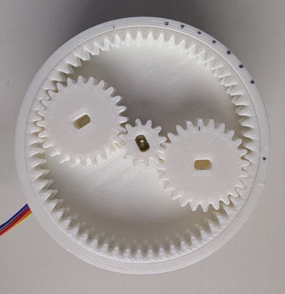
The field is just a provider the place you place in every little thing. I superglued the decrease ring to the field. As well as I additionally superglued the motor to the again aspect with its shaft sticking contained in the gearbox. Right here is a picture of the completed product.
Subsequent steps
Within the subsequent weblog I’ll go over the Arduino setup to get all of it shifting. At this stage the entire field is open on the highest. The output ring has no output linked. It’s simply there to easily watch, and display the working idea.


